
Cuprite
11/1/2025 - Intial Design Ideas, Frame, Gantry Components
So this is a full redesign of my highway printer:
https://github.com/Renovic/Cuprite-OLD-
.png)
.png)
.png)
There are a couple of things that happened that made me want to redesign: - Sponsors: I reached out to a couple of companies and I got some sponsors which means I needed to change a couple of parts. The companies are: LDO, Sunlu, JLCPCB(OSHWLABS), BST AUTOMATION, Filastruder - Makerspace access: Now I have access to a makerspace and a source for sheetmetal so I have access to more manufacturing capabilities - Better Design Ideas: My original design was rushed and wasn't ideal. For example, the toolhead COM wasn't next to the carriage, so it would lead to worse results. - Better Aesthetics: I've gotten a lot of new ideas for improved aesthetics
Day 1- Full Redesign Concept (Oct 1st - 3rd)
Over these few days, I consolidated my ideas on what I wanted to redesign. I also started sourcing parts for the build.
So here are all of the changes from the old version I plan:
Frame:
2020 + 2040 - > 4040 verticals (JLCMC) - This will imporve rigidity greatly and allow for better mounting
Insulation/Panels:
No Insulation -> 3/4" PIR Insulation - Fits inside of the frame, which is why 4040 verticals are important
Gantry:
9mm belts -> 12mm EPDM (partialy sponsored by Filastruder) 2WD -> 4WD (Sponserd by LDO) 1/8" Alu sheetmetal -> CNC aluminum (JLCCNC) 2020 extrusion x-gantry -> 2030 aluminum tube - Should allow for more rigidity - ~30% Input Shaper gain from 9mm -> 12mm belts - ~100% Input Shaper gain from 2WD -> AWD - More Input Shaper gain from extra frame, and gantry rigidty
Toolhead:
Peopoly Lancer -> Custom aluminum hotend (JLC3DP) Fully SLM/CNC toolhead (JLC3DP & JLCNC) G2 Extruder (LDO) - Better extrusion from G2 - More rigidity from bottom supported hotend - Centered COM from redesign - higher flow rate
Cooling:
WS7040 -> 130k RPM Ducted Fan No flap -> Stepper motor flap - Cheaper - Higher max cfm
Z Axis
In chamber motors -> bottom-mounted motors BMG Gear Reduction -> G2Z 3dp joints -> slm joints (JLC3DP) No spring tension -> spring holding down bed frame to joints Extrusion bed frame -> Laser cut aluminum frame - More rigidity - More travel from bottom-mounted z motors - Better z motion consistency, and as a result better layer stacking
Electronics
Fystec Spider -> Leviathan + Expansion board (sponsored by LDO) tmc2209 XY motor drivers -> tmc5160 XY motor drivers (Built in to Leviathan) 24V XY -> 48V XY (Partially sponsored by Filastruder) 0 mainboard cooling -> 4x 6020 fans (JLCMC) - Higher stepper motor speeds - Better step control - Can cool stepper motors
Chamber Heater
None -> 100W Chamber Heater - Cheap - Allows for good chamber temps
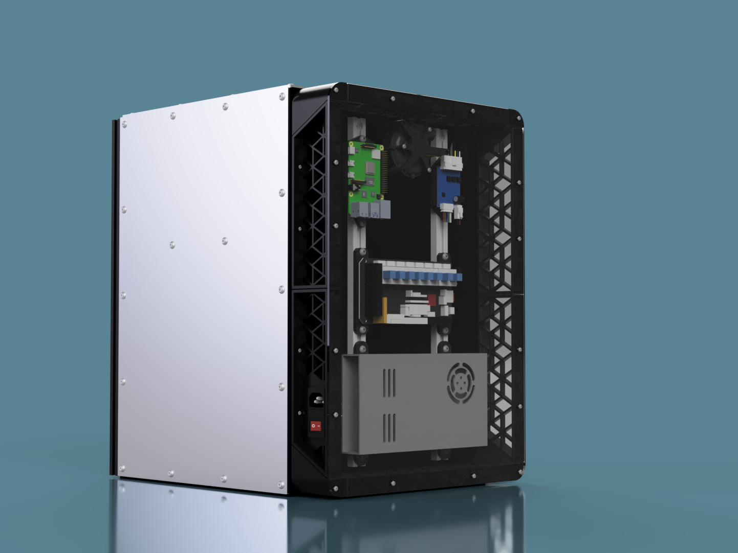
Aesthetic Improvements
Rear backpack -> top and bottom electronics enclosures Exposed panels -> printed covers Door hinges integrated into panel covers - Displays Leviathan and good looking electronics on top - Hides PSUs underneath - Nicer visuals
Even with all of these improvments, the cost of new components should be cheaper than the original.
Hours Spent: 12 Total: 12
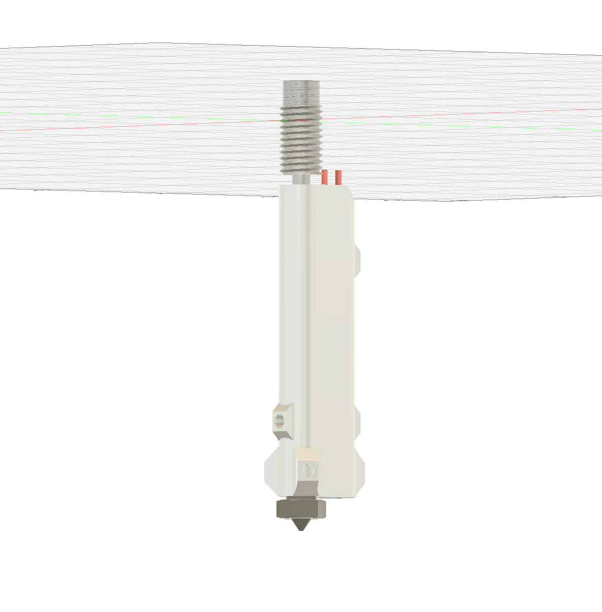
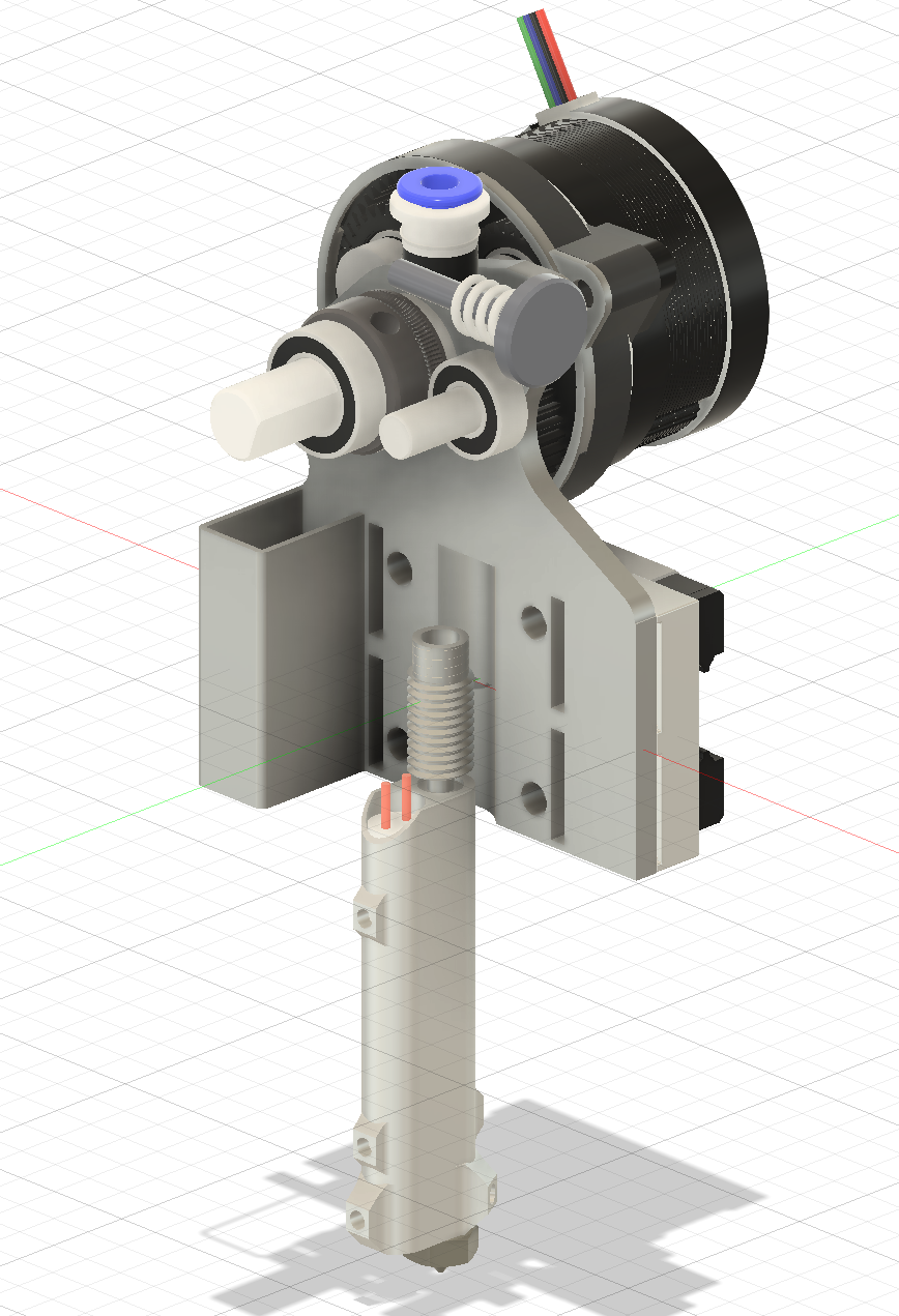
Day 2 - SLM Toolhead Redesign Concept (Oct 13th)
I started by designing a hotend similar to the hotend in the monolith toolhead, or DK's slm bmg toolhead. This should get high flow rates and have mounting for a bottom hotend brace. I spent the rest of the time messing around with different extruder options, and hotend locations to find anything that could get me a good com and nice design. The main issue was with bmg gears the gear covers the bolts mounting the main toolhead body into the mgn12h carriage. I also wanted to try using a g2e kit because it should give me very precise extrusion without any wood grain affect thats normally caused by double gear extruders. Although I didn't get as much as I wanted done, I was able to figure out the location of the hotend and extruder that could give me a decent center of mass, and I got some ideas of the rest of the design.
Hours Spent: 6 Total: 18
Day 3 - CNC Front Motor Mounts (Oct 17th)
Main Goal for this was component was to incorperate the front extrusion brace and rigid part. This is using the monolith belt path like before, but now for 12mm belts. Also I made sure to insert every fastener required so I can make sure I source all of the components and don't have any intersections. But this made it take a bit longer than how I was designed previously. During this day, I also found sources for the hardware required, most of the hardware like bearings, standoffs, and bolts were from JLCMC.
Hours Spent: 4 Total: 22
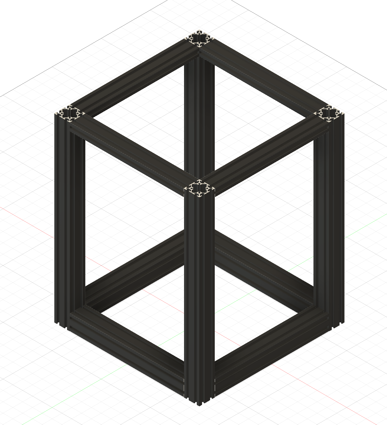
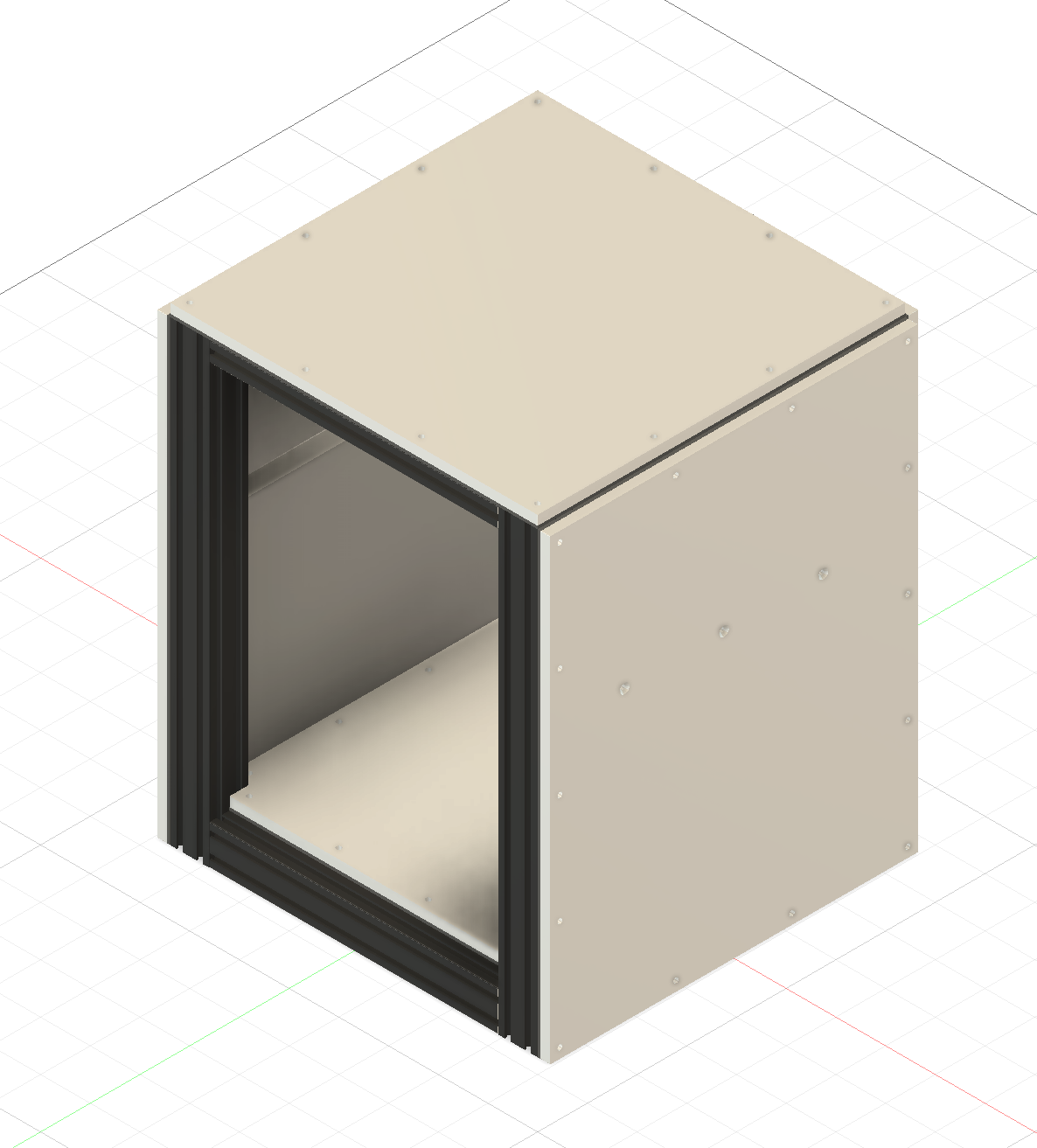
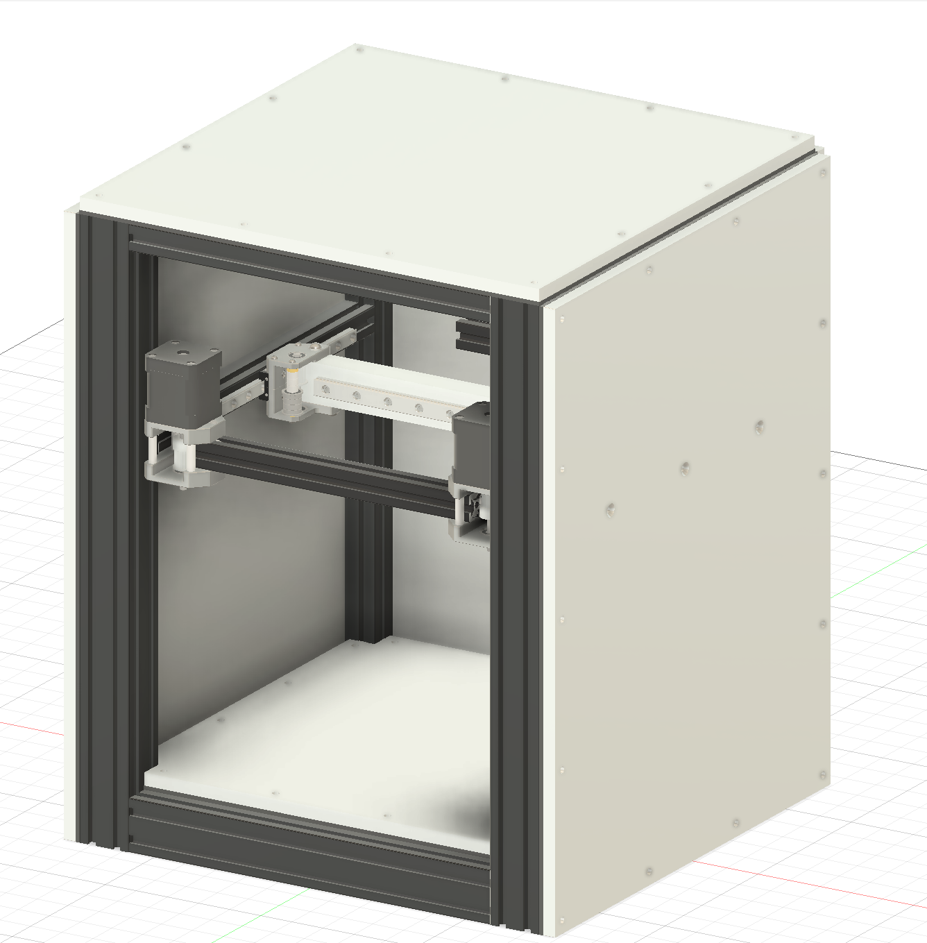
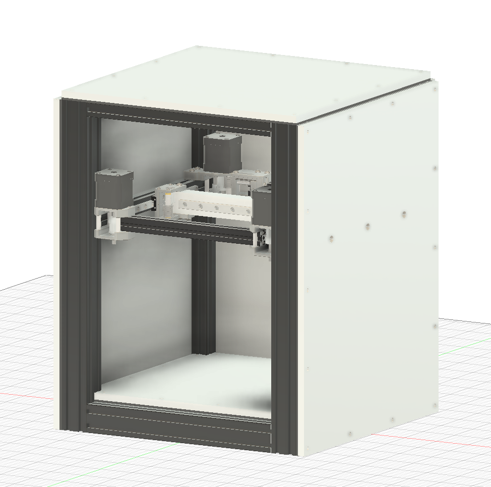
Day 4 - New Frame & Panels (Oct 30th)
I redesigned the Frame to use 4040 verticals. I also was able to find 3/8" aluminum panels, so I designed the aluminum panels to be mounted onto the frame. Another thing I realized I missed on the first design is the rubber strips to reduce heat and vibration transfers from the frame to panels, so I designed those in. Finally I added insulation to the internal faces of the panels. The overall width of the printer is 50mm wider than the orignal printer, but it includes insulation.
Hours Spent: 2.5 *Total: 24.5
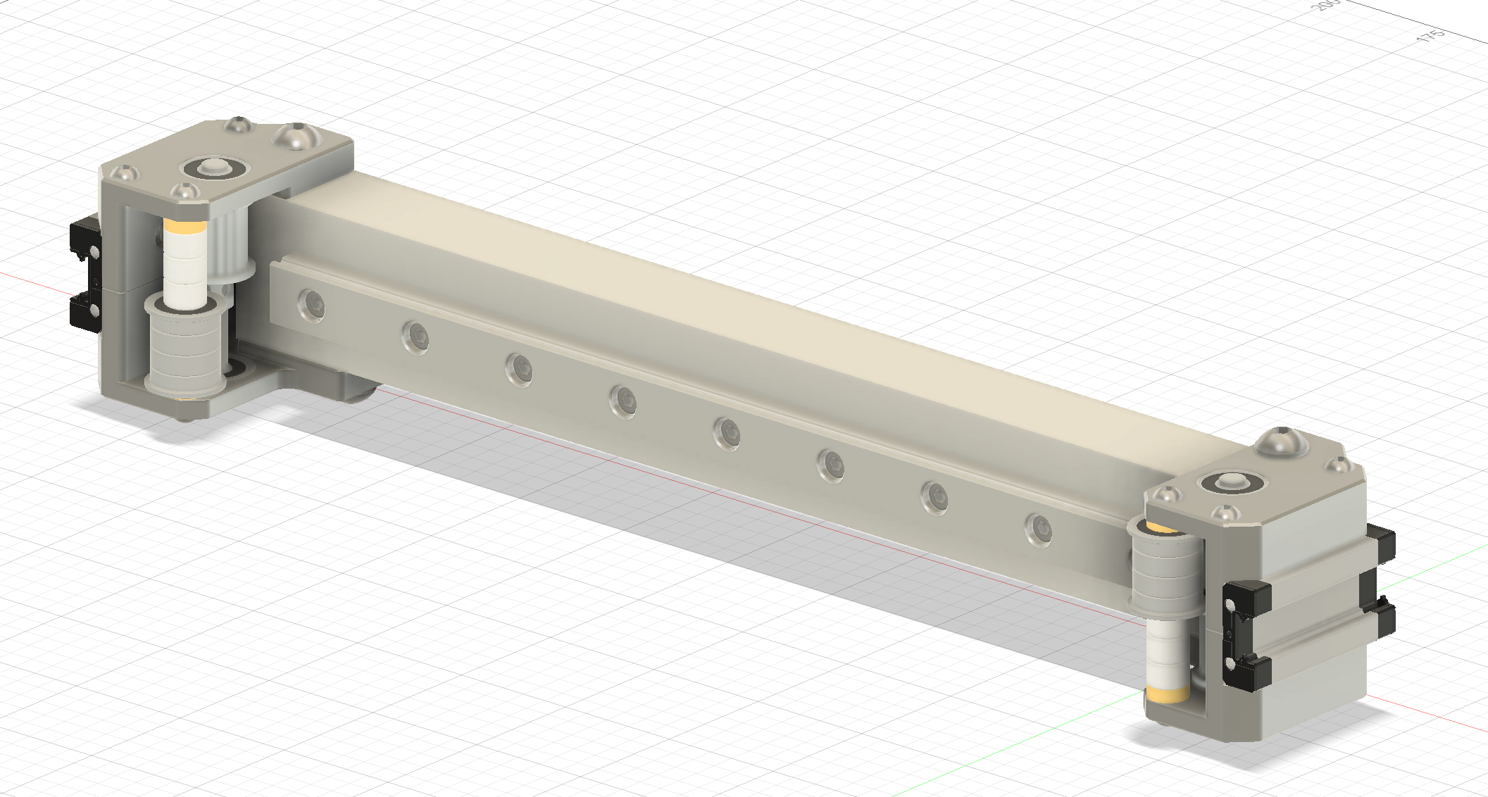
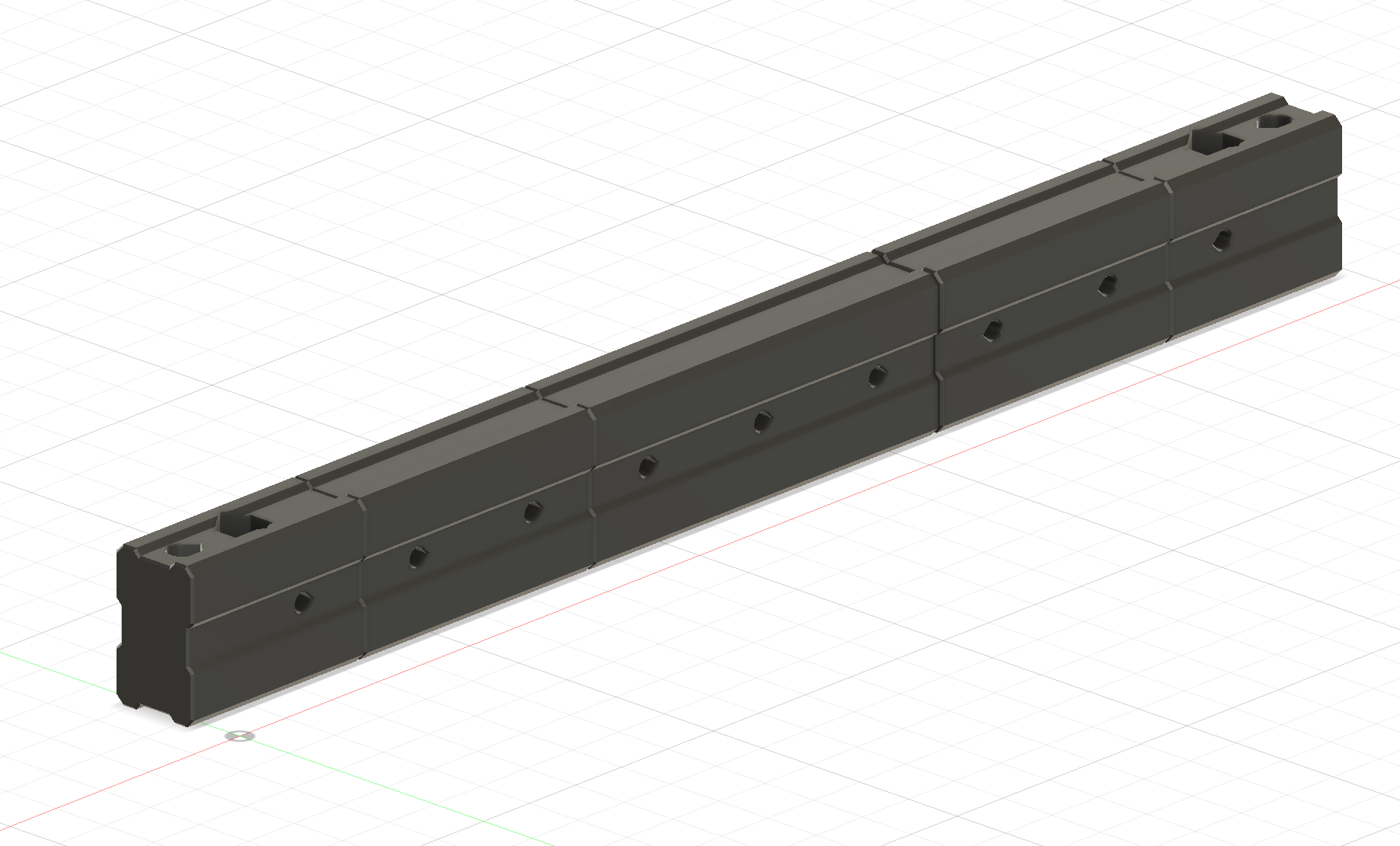
Day 5 - X Axis (Oct 31st)
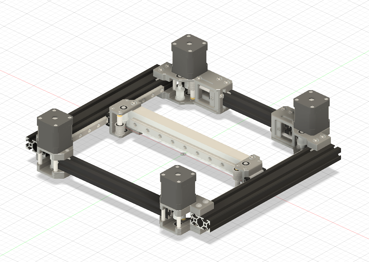
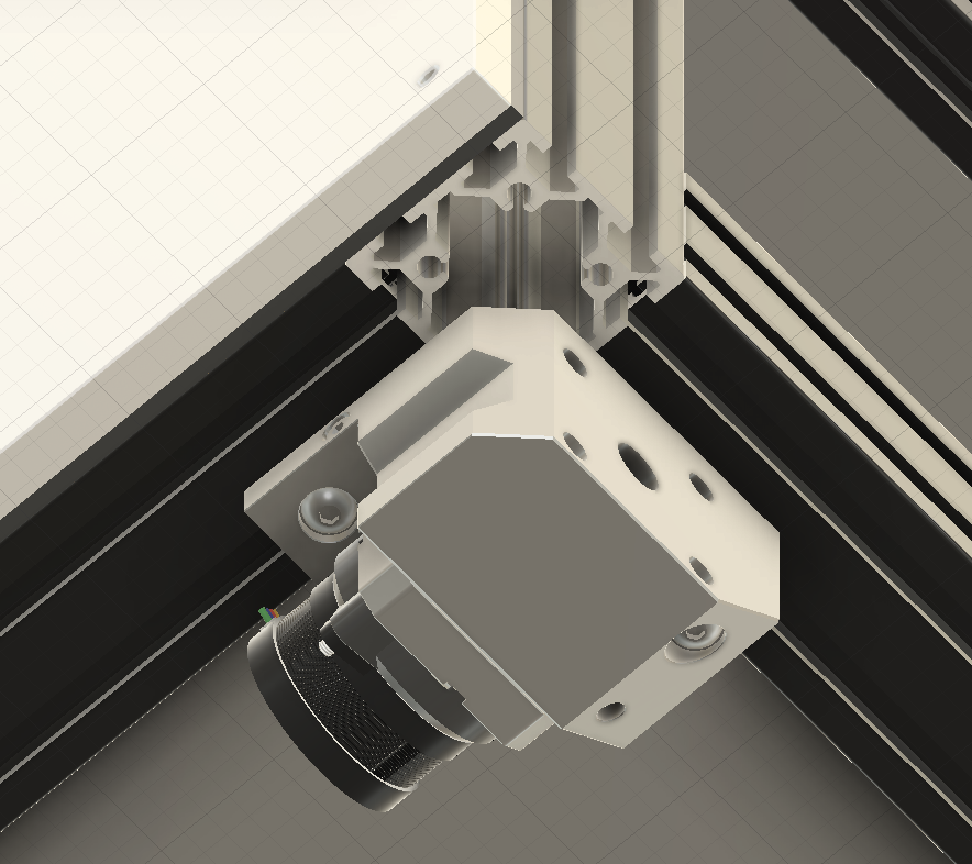
Today I redesigned the X axis and XY joints to use 12mm belts and 2030 Aluminum Tube. The XY joints are 2 part that clamp onto the mgn9h carriage and bolt into the carriage. Then I made the 2030 aluminum tube and mounting hardware. I also needed to add 3d printed crush blocks into the tube so I can mount the rail to the tube without worrying about bending the tube inwards. I also found the sources for aluminum tube, hardware and compression springs for correct spacing on the live idler joint.
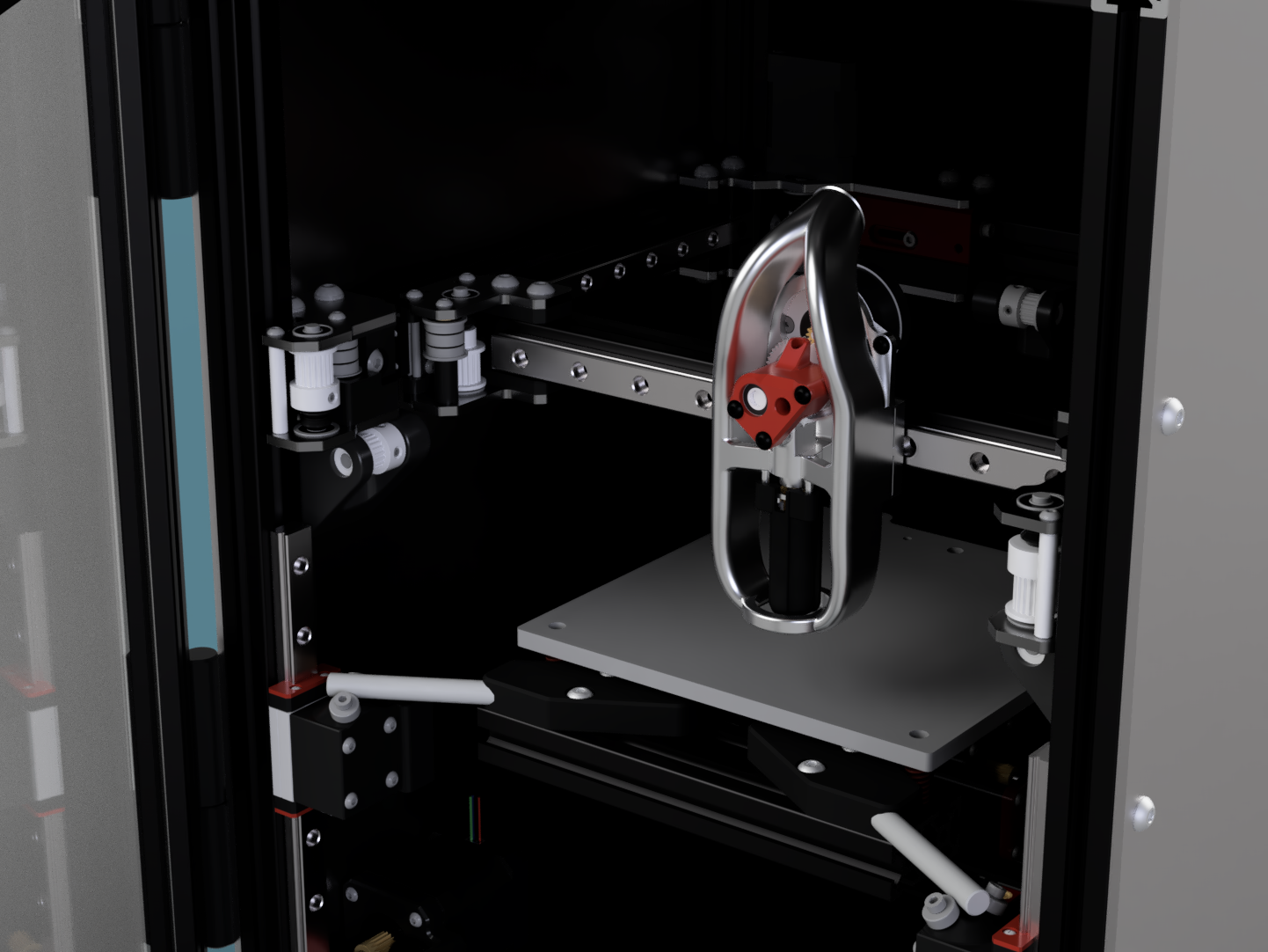
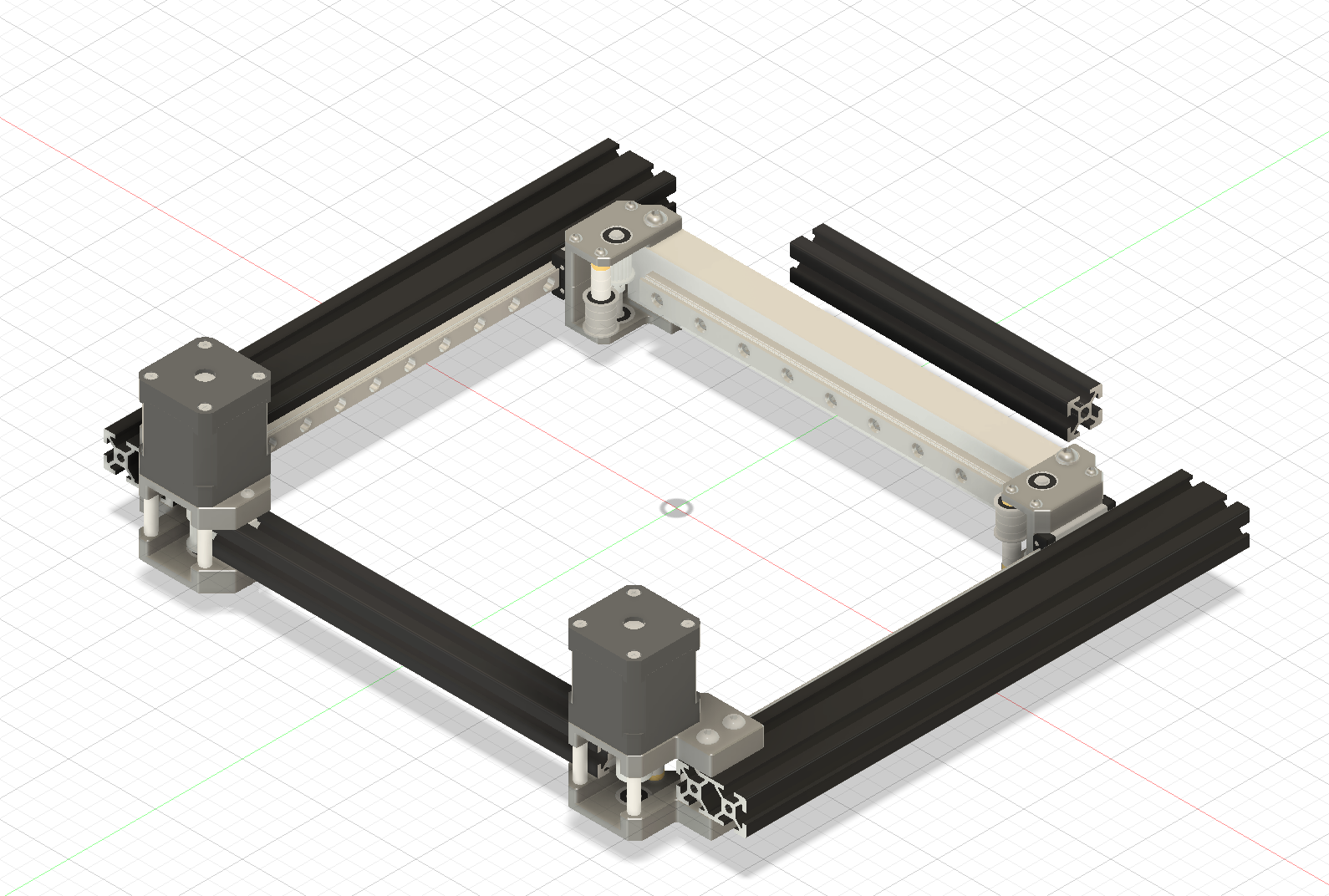
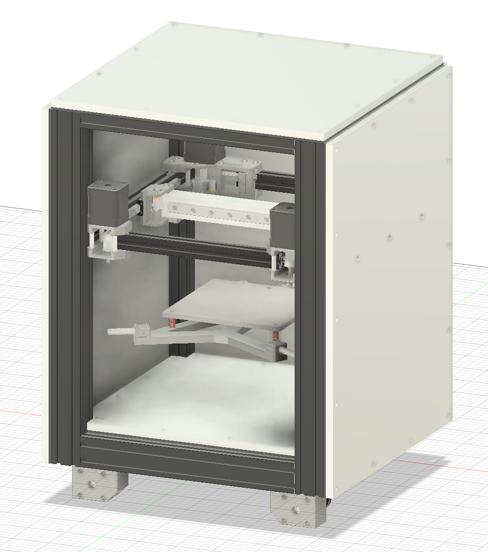
Then I wanted to see how the gantry looked, so I made a gantry assembly and put it into the frame.
Hours Spent: 5.5 Total: 31
11/2/2025 - Designing Rear Motor Mounts
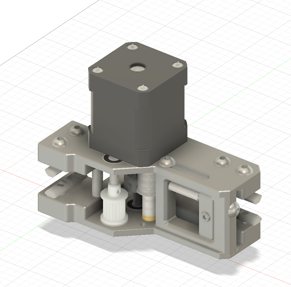
Day 6 - Rear Motor Mounts (Nov 1st)
I was really confused about how to design the CNC belt tensioner for a while. But I finally had an idea to use slots to guide the tensioner, have a countersunk M3 screw to mount the tensioner bearing stack pin, and M5 bolts to clamp the tensioner in place.
These took way longer than I expected because of the amount of hardware required for this part.
Hours Spent: 6 Total: 37
11/3/2025 - Bed Assembly, Front Z drives
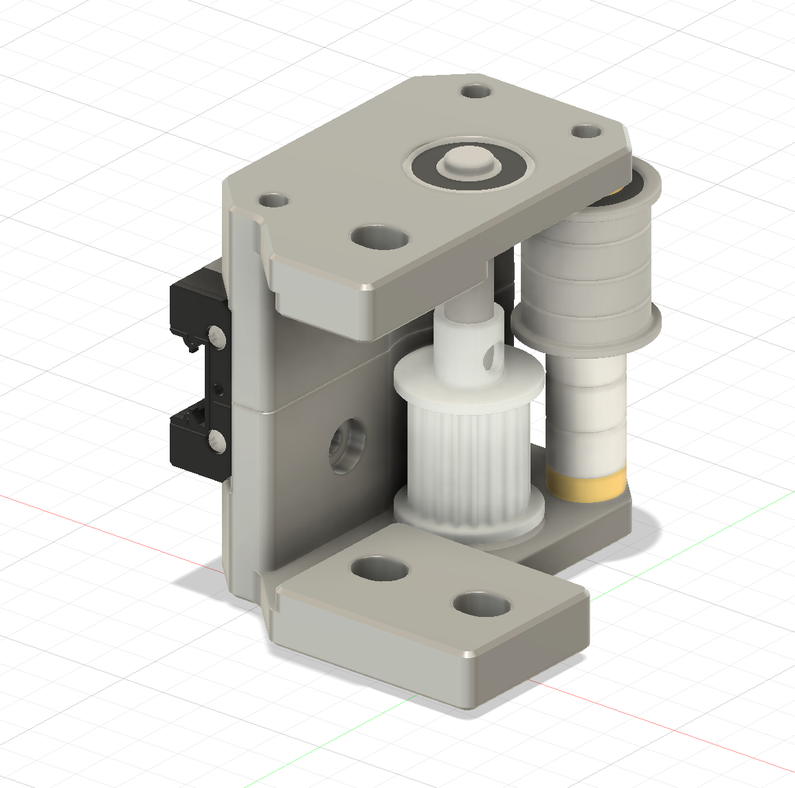
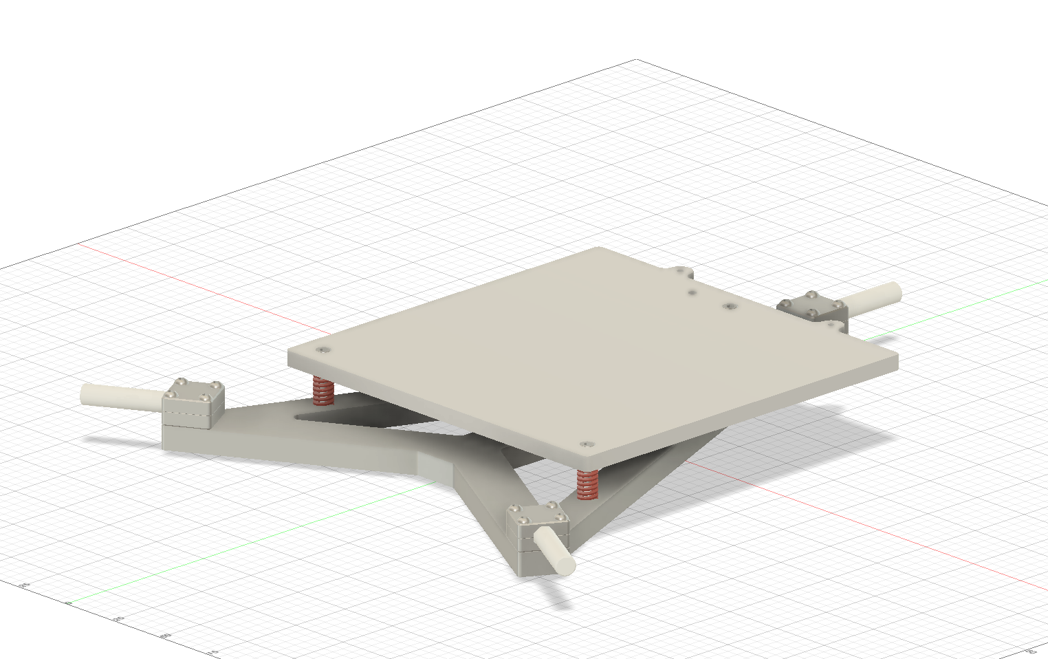
Day 7 - Bed Assembly, Front Z drives (Nov 2nd)
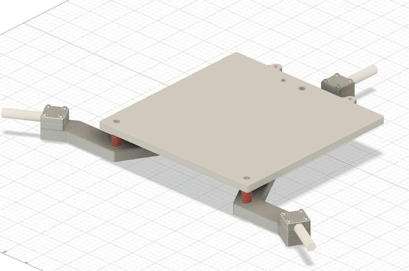
I started by designing the bed assembly. It uses a sheet metal carriage and some CNC components to mount the bed and 8mm rods that will be used for kinematic coupling.
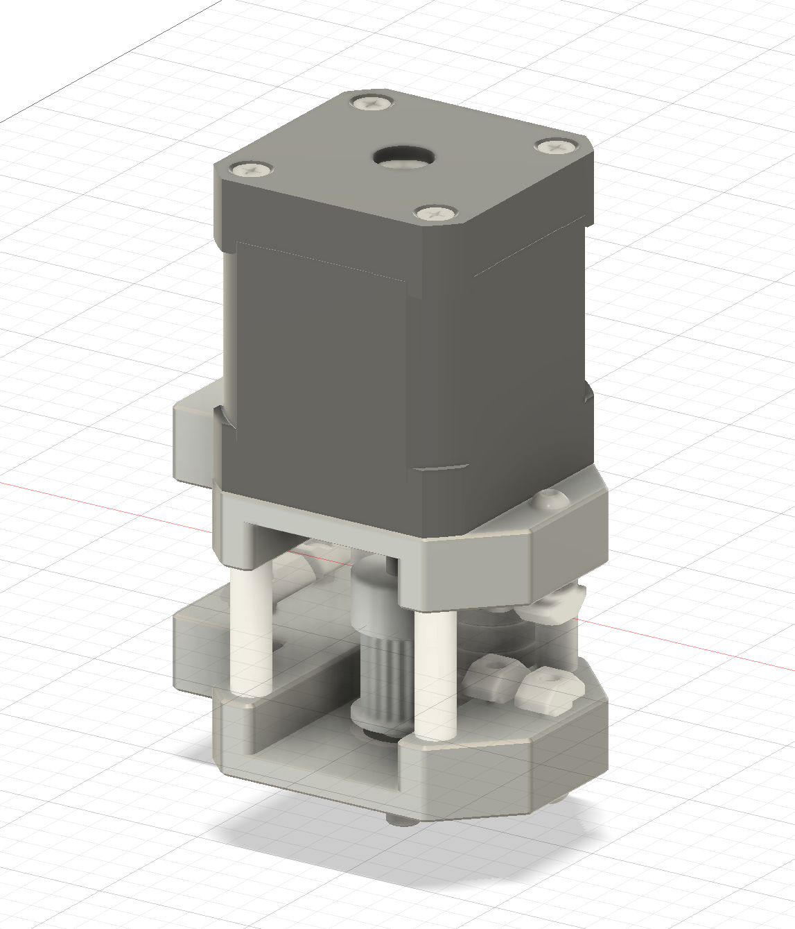
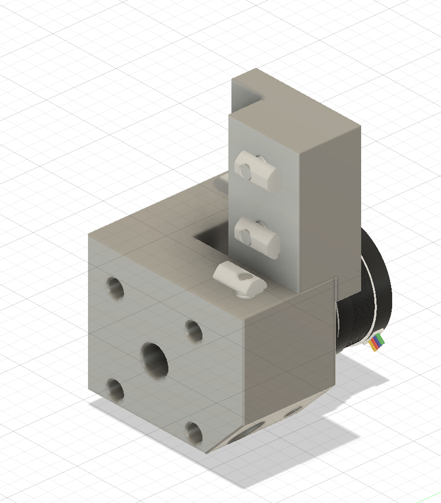
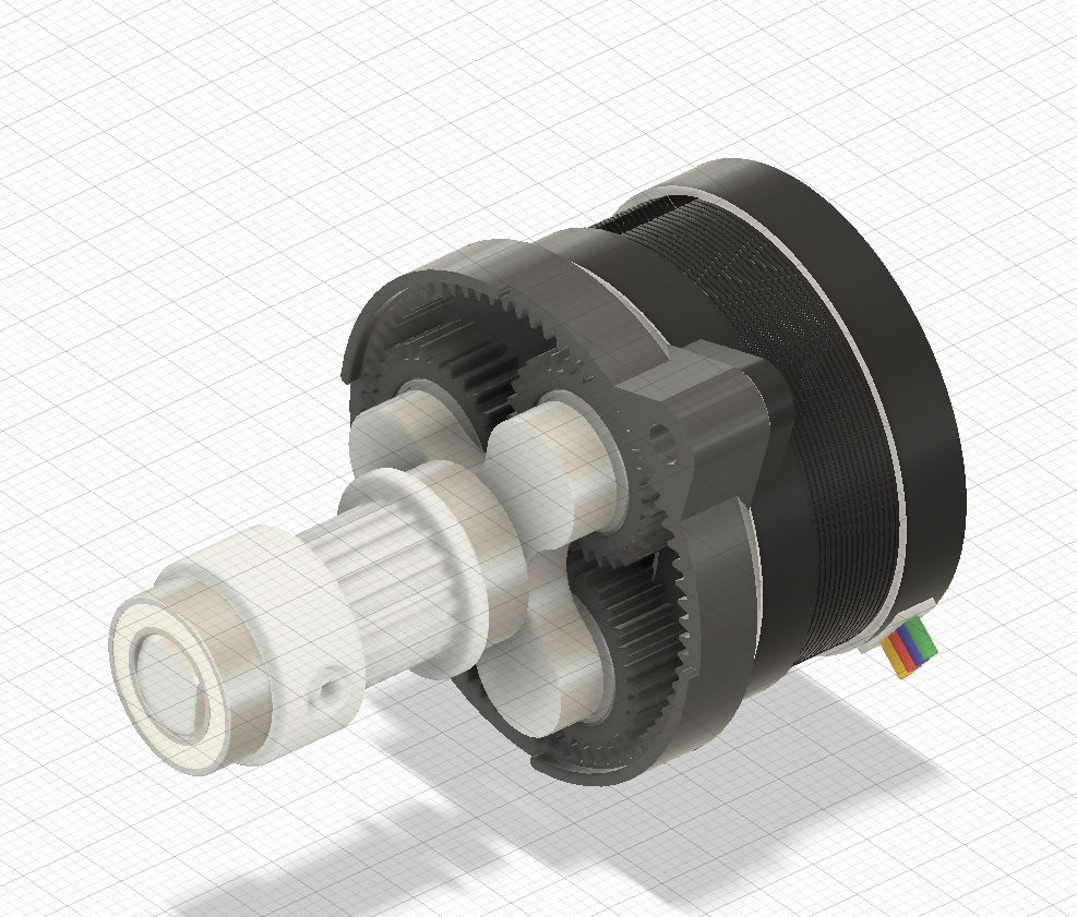
Then I designed the front Z drives that use G2Z planetary gearboxes for precise Z motion. Part of the design was making sure the part is entirely sealed so air from the chamber can't leak into the bottom electronics area.
Hours Spent: 6.5 Total: 43.5
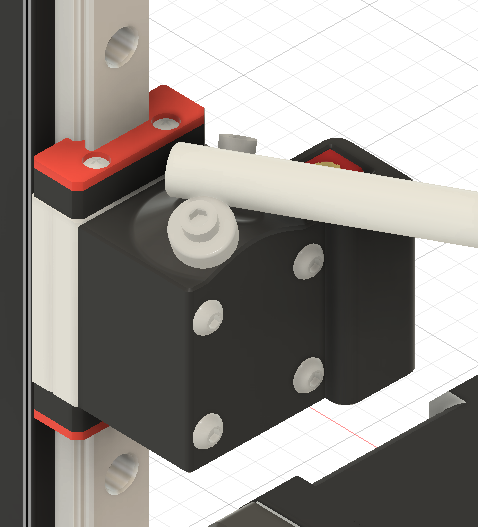
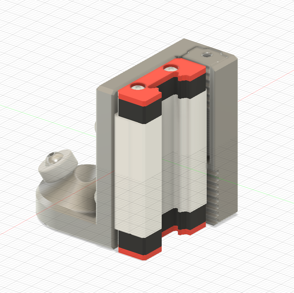
11/5/2025 - Day 8 - Back Z drives, Tweaks to Z axis, More research
Day 8 - (Nov 4th)
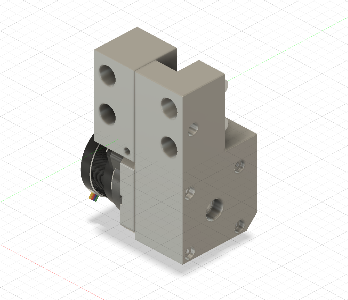
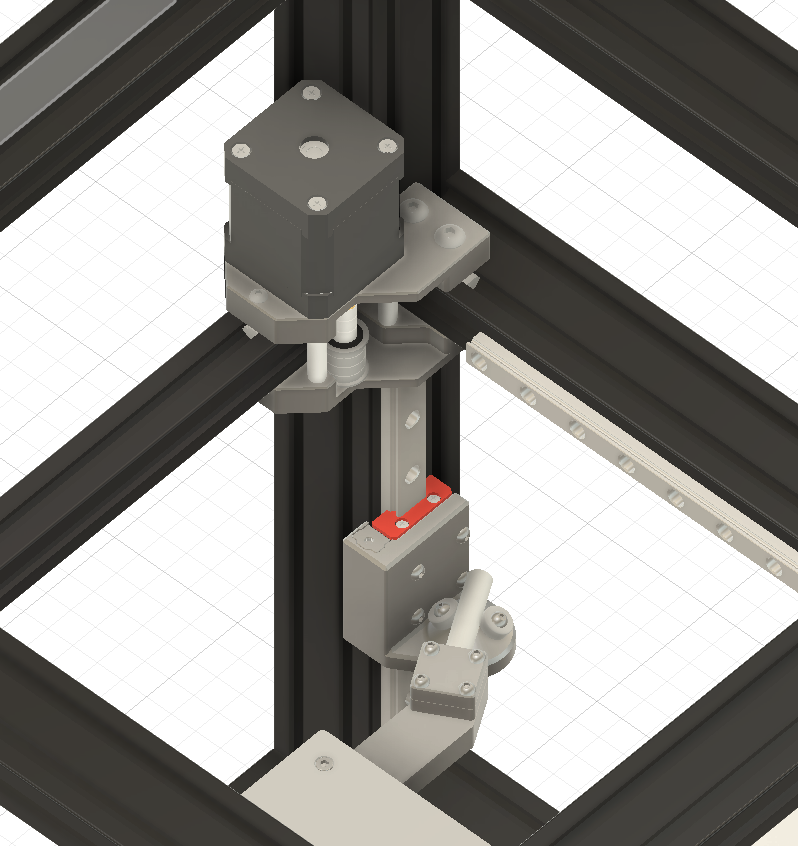
I started with designing the rear Z drive, and this was pretty similar to the front Z drives, but mounted differently.
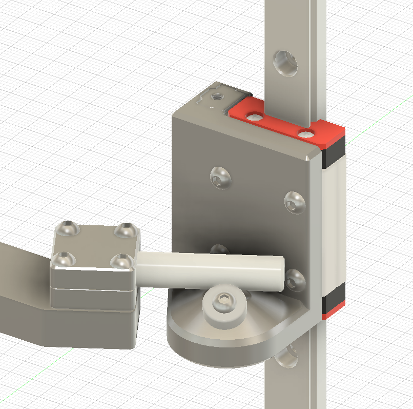
Then I started thinking about how I was going to do the Z belt tensioners. Although I originally just planned on designing a belt tensioner similar to the Annex K3 z-axis tensioners, I wanted to see if there was something more compact. So I did some research and found Hex 0 had some very compact belt tensioners.
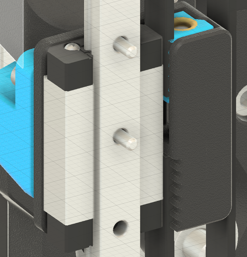
These tensioners pressed the belt against the linear rail carriage and had one part slide to adjust tension. The Hex 0 z drives used 6mm belts and mgn7 rails, so I was a bit concerned about whether this would work. But thankfully, I found that the mgn12 rails had enough width for 9mm belts. I had to adjust the front z drive pulley location to make the belt line up with the edge of the carriage. I also added some channels for wires to come down the vertical 4040 extrusions, and go to the stepper. 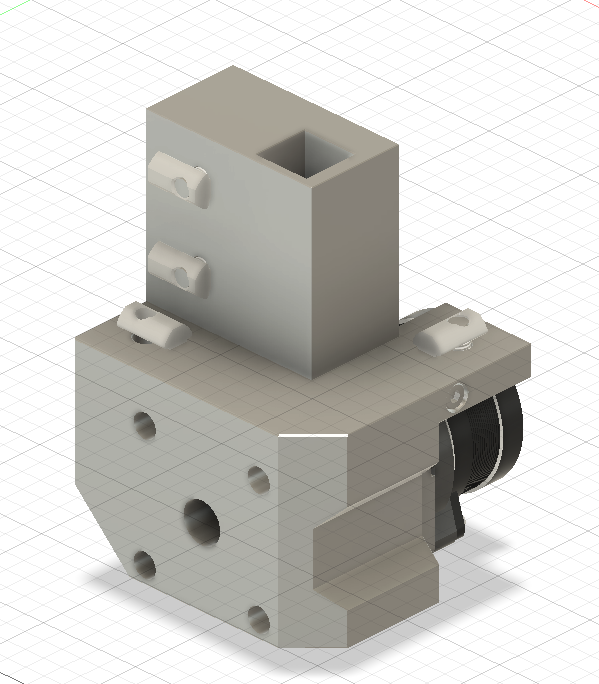
Then I went to make some tweaks to the bed carriage. I was a little concerened about the weight because I was using 3/8" thick aluminum and my original design was very beefy, so I checked and it was 400 grams. I decided to redesign it to be a little simpler and much lighter, and it ended up being 250 grams.
Finally, I started thinking about how I would get the most travel possible. So I measured out the toolhead length, z joint length and bed height and found that I only had 104mm of travel. The 200mm rail I have has a full travel of 150mm, so Im losing out on a lot. My two ideas so far are to raise the rod mounts on the bed assembly, to effectively drop the bed down, or redesign the z joints with the bearing further down.
For reference: my original z joints (I have to redesign these for slm printing, different tensioner, and 9mm belts)
** Hours Spent: 5.5 ** ** Total Hours: 49 **
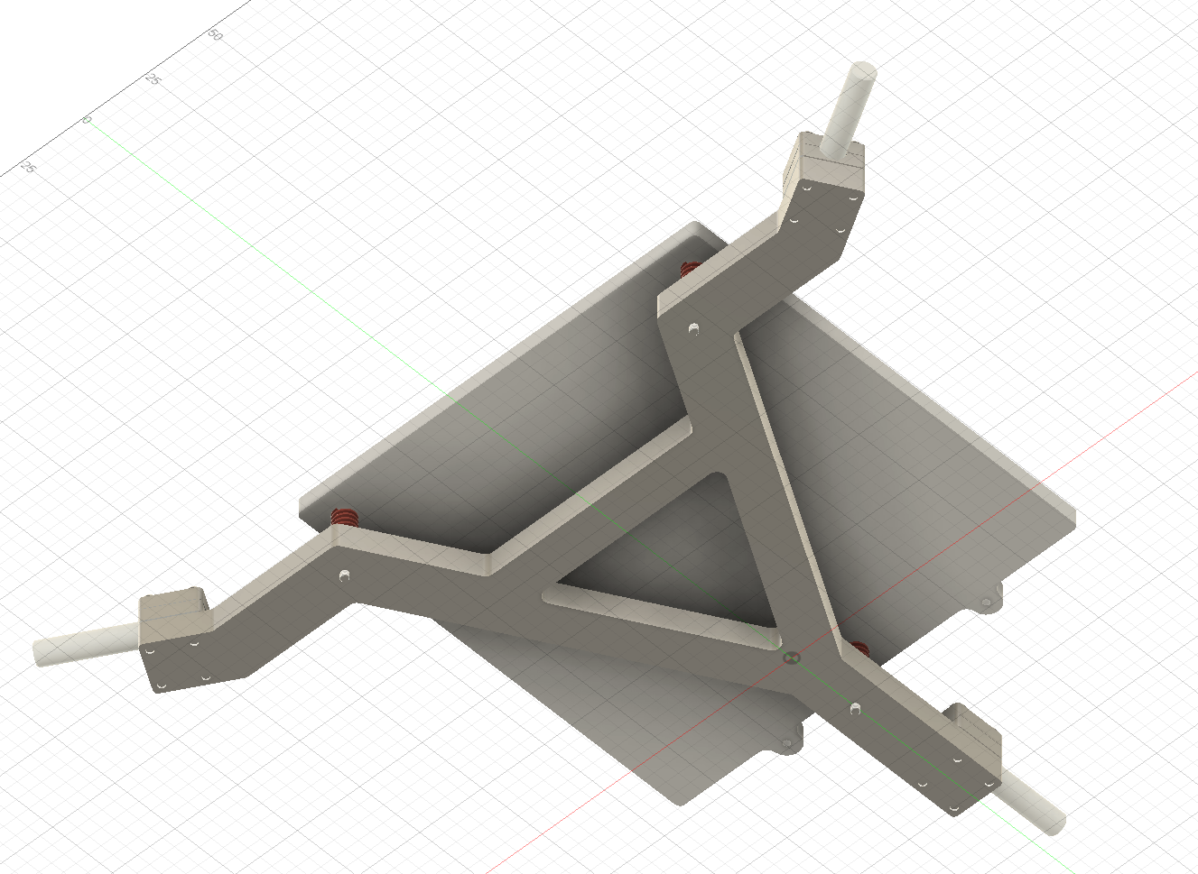
11/6/2025 - Day 9 - Front Z Joint
Day 9 - (Nov 5th)
My main goal was to finish the z joints, but this one z joint took a lot longer than I was expecting.
Yesterday, I found that the bed travel would be significantly limited if I went with my previous idea of the 8mm rods resting on top of the z joint rails, so I was trying to come up with a way to move the 8mm rod mount further down to increase Z travel. Eventually, I came up with a decent idea and designed it.
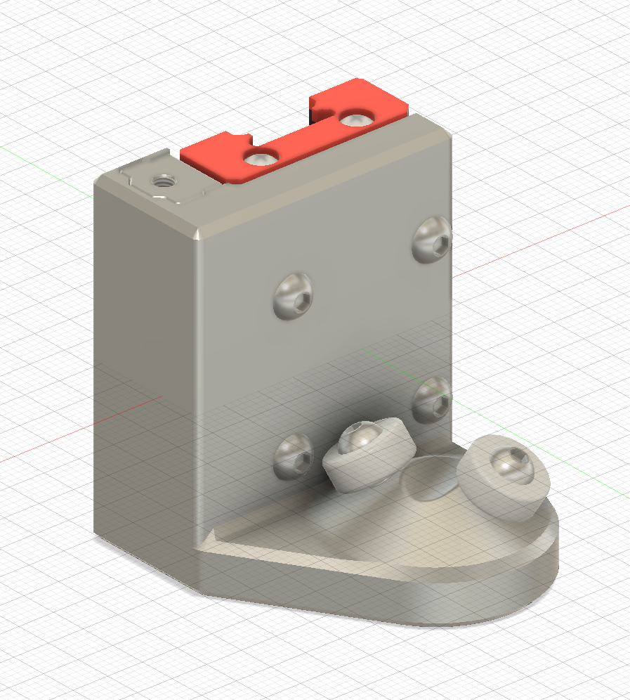
With this design I should be able to get 135mm of travel, which I think is acceptable. The only way I can increase z travel after this is by decreasing the bed assembly thickness (currently 30mm), or increasing the height of the overall printer, which I don't think is worth it for an extra 15mm of travel.
I also had to adjust the bed carriage again slightly to match the new position of the 8mm rod mounts.
The problem with this design is that I don't have a spring keeping the 8mm rod pressed against the bearings. The bed's weight will hold it down, but it is only a 160mm bed so it isn't very heavy, so I need some springs to hold it down. I wasn't sure how to implement it while designing the main part of the Z joint, so I'll try to add it next time.
Hours Spent: 3 Total Hours: 52